2. Dual Legged Routing Mode Example
Dual Legged Routing Mode Network Overview
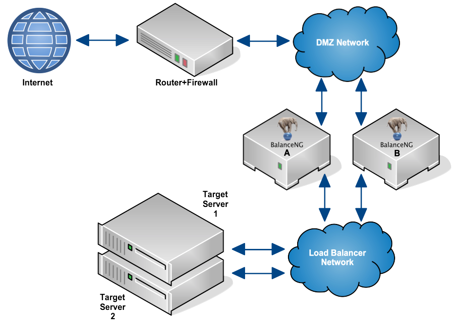
In this example we use exactly the same network settings as in Example 1, but instead of operating everything in one physical LAN, we establish a second, separate LAN for load balancing. Additionally, we are configuring two BalanceNG nodes with VRRP in order to achieve high availability.
The configuration then looks as this (switches not shown):

Network Configuration Overview - Dual legged Routing Mode
The Configuration Files
BalanceNG Node A
//        configuration taken ...
//        BalanceNG ...
modules   vrrp,arp,ping,hc,master,slb,tnat,nat,rt
set       ipforwarding 1
interface 1 {
          name eth0
          access raw
}
interface 2 {
          name eth1
          access raw
}
register  interfaces 1,2
enable    interface 1,2
vrrp      {
          vrid 71
          priority 200
          network 1
}
network 1 {
          name "DMZ Network"
          addr 172.16.1.0
          mask 255.255.255.0
          real 172.16.1.251
          virt 172.16.1.253
          nat outside
          interface 1
}
network 2 {
          name "LN Network"
          addr 10.1.1.0
          mask 255.255.255.0
          real 10.1.1.252
          virt 10.1.1.254
          nat inside
          interface 2
}
register  networks 1,2
enable    networks 1,2
gateway   {
          ipaddr 172.16.1.254
          ping 3,8
}
server    1 {
          ipaddr 172.16.1.10
          port 80
          protocol tcp
          targets 1,2
}
register  server 1
enable    server 1
target    1 {
          ipaddr 10.1.1.1
          port 80
          protocol tcp
          tcpopen 80,3,10
}
target    2 {
          ipaddr 10.1.1.2
          port 80
          protocol tcp
          tcpopen 80,2,10
}
register  targets 1,2
enable    targets 1,2
//        end of configuration
BalanceNG Node B
//        configuration taken ...
//        BalanceNG ...
modules   vrrp,arp,ping,hc,master,slb,tnat,nat,rt
set       ipforwarding 1
interface 1 {
          name eth0
          access raw
}
interface 2 {
          name eth1
          access raw
}
register  interface 1,2
enable    interface 1,2
vrrp      {
          vrid 71
          priority 200
          network 1
}
network   1 {
          name "DMZ Network"
          addr 172.16.1.0
          mask 255.255.255.0
          real 172.16.1.252
          virt 172.16.1.253
          nat outside
          interface 1
}
network   2 {
          name "LN Network"
          addr 10.1.1.0
          mask 255.255.255.0
          real 10.1.1.253
          virt 10.1.1.254
          nat inside
          interface 2
}
register  networks 1,2
enable    networks 1,2
gateway   {
          ipaddr 172.16.1.254
          ping 3,8
}
server    1 {
          ipaddr 172.16.1.10
          port 80
          protocol tcp
          targets 1,2
}
register  server 1
enable    server 1
target    1 {
          ipaddr 10.1.1.1
          port 80
          protocol tcp
          tcpopen 80,3,10
}
target    2 {
          ipaddr 10.1.1.2
          port 80
          protocol tcp
          tcpopen 80,2,10
}
register  targets 1,2
enable    targets 1,2
//        end of configuration
Testing
- You should be able to ping the default gateway 10.1.1.254 from the targets.
- You should be able to ping the virtual web server 172.16.1.10 from the router.
- Clients from the Internet are able to initiate TCP connection to port 80 on the virtual Web Server 172.16.1.10 (now being represented by BalanceNG). “show servers” and “show targets” in BalanceNG interactive mode should show everything up and operating.